SPART Tutorial – Introduction
This tutorial covers the basic functionality of SPART and introduces some concepts of multibody systems. The tutorial is structured in three sections:
- Introduction – Covers the nomenclature and conventions used by SPART.
- SPART Tutorial – Robot Model – Covers the URDF description of a multibody system and the SPART
robotstructure. - SPART Tutorial – Kinematics – Covers the kinematics – positions, orientations, velocities, and accelerations – of the system.
- SPART Tutorial – Dynamics – Covers how to obtain the inertia matrices, equations of motion, and solve the forward/inverse dynamic problem.
The code in this tutorial can be found in examples/URDF_Tutorial/URDF_Tutorial.m.
Note
Before starting this tutorial make sure you have correctly installed and configured SPART. See Installing SPART for instructions.
Kinematic tree topology
A multibody system is defined as a collection of bodies coupled by massless joints. The bodies of the system – also known as links – are arranged in one of two basic types of kinematic chains:
- Kinematic trees, when the path between any pair of links is unique. This are also known as open-loop kinematic chains.
- Closed-loop kinematic chains, when the path between any pair of links is not unique.
SPART is only able to handle multibody systems composed of rigid bodies arranged in kinematic trees.

Kinematic tree.
Joint/Link nomenclature and numbering scheme
A link is denoted by \(\mathcal{L}_{i}\) and a joint by \(\mathcal{J}_{i}\), with the number \(i\) used as a unique identifier of each link or joint. In SPART, the number \(i\) is used to access the results associated with a specific link or joint.
In a kinematic tree, one of the links is designated as the base-link, with \(i=0\) and \(\mathcal{L}_{0}\). The base-link can be selected arbitrarily among all the links, yet an obvious choice usually exists.
A link \(\mathcal{L}_{i}\) can be connected with an arbitrary number of other links via an equal number of joints. Only one of these other links lies within the path connecting \(\mathcal{L}_{i}\) and the base-link \(\mathcal{L}_{0}\). This previous/upstream link \(\mathcal{L}_{i-1}\) is known as the parent link of \(\mathcal{L}_{i}\) and the joint connecting these two links is \(\mathcal{J}_{i}\). The rest of links directly connected to link \(\mathcal{L}_{i}\) are child links \(\mathcal{L}_{i+1}\). A branching event occurs when a link has multiple children.
In the regular number scheme used by SPART, each children link is given a higher number \(i\) than its parent, with the base link given the number \(i=0\). In a branching event multiple numbering options exist and they can be chosen arbitrarily among them. The notation \(i+1\) and \(i-1\) is here abused to denote the child and parent link or joint, even when they are not sequentially numbered. Additionally, the total number of joints \(n\) is also used to refer to the last joint and link of a branch. The last link of a branch is also commonly referred to as an end-effector.

Regular numbering scheme.
Joints types
Three type of joints primitives can be modeled with SPART:
- Fixed – a joint rigidly connecting the pair of links (zero degrees-of-freedom).
- Revolute – a joint that allows a rotation around a common rotation axis \(\hat{e}_{i}\) (one degree-of-freedom).
- Prismatic – a joint that allows a translation along a common sliding axis \(\hat{e}_{i}\) (one degree-of-freedom).
More complex joints (e.g., planar, spherical, helical, …) can be constructed as a combination of these primitive joints connected by massless and dimensionless links.
Only revolute and prismatic joints are active joints, with the rotation or translation displacement denoted by \(q_{i}\).
Cartesian Coordinate Systems (CCS)
Each link and joint has an associated Cartesian Coordinate System (CCS). The origin of the link CCS is located at the link’s center-of-mass, and the origin of the joint CSS is located on the rotation/sliding axis. The orientations of the CCS are arbitrary.
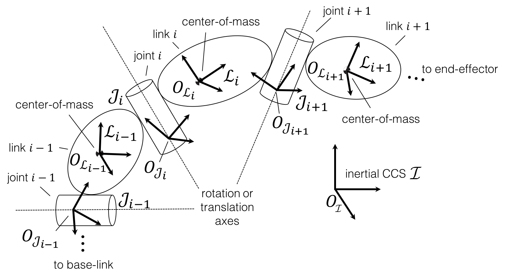
Cartesian Coordinate Systems.
Joint displacements
Another convention in SPART is that a displacement on a joint affects all the elements downstream, but it doesn’t affect the orientation or position of that joint CCS.
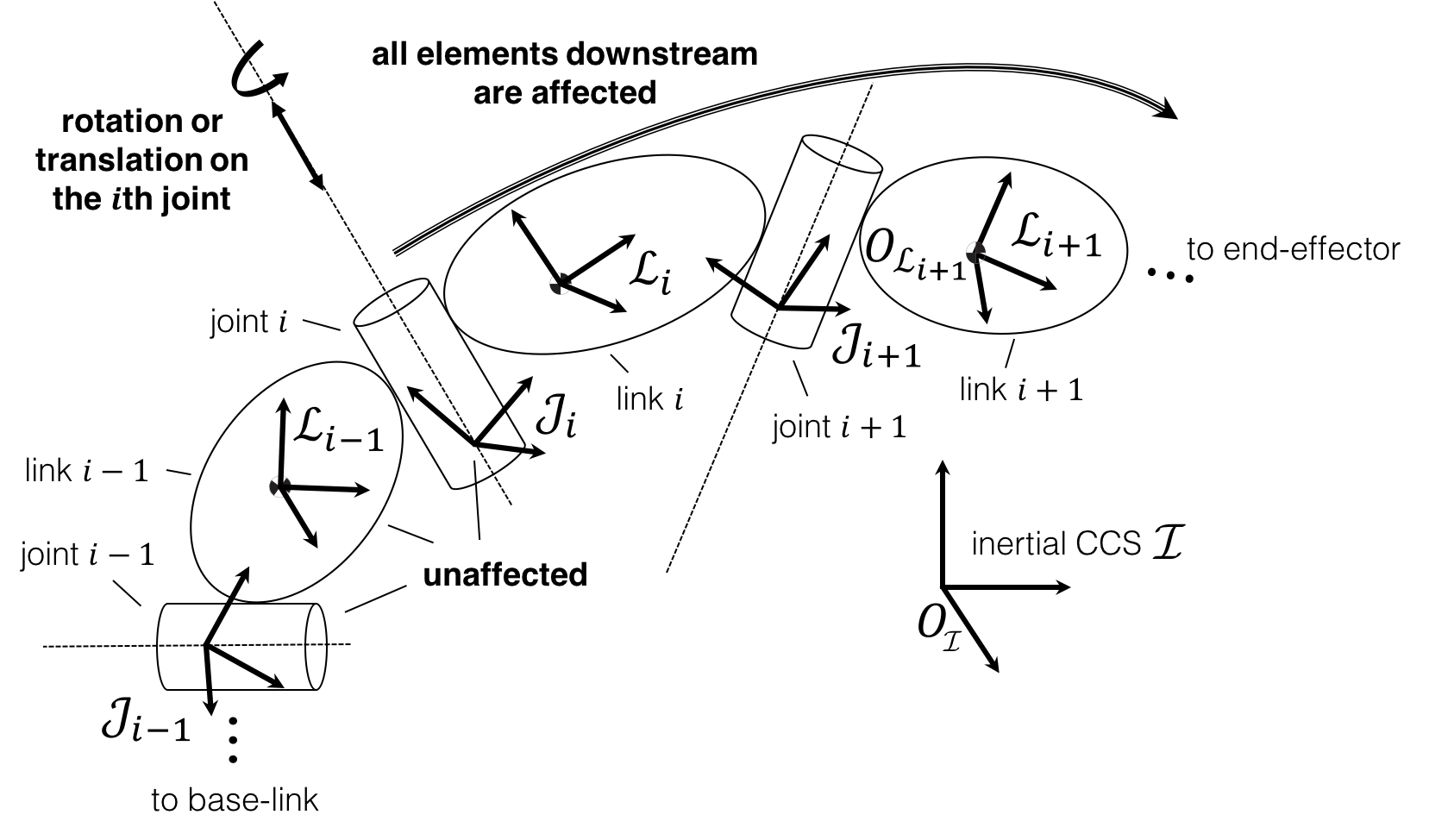
Effects of a joint displacement.